User Tools
Table of Contents
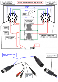
Pinout:
The misterious MELBUS.
Physical Interface
Melbus physical interface consists of 3 lines:
- MSCK - the clock signal
- MDATA - the data signal which carries information
- MBUSY - indicates whether the data signal is busy or not
These lines are in HIGH idle state.
The communications on Melbus are implemented on NEC microcontrollers.
HU-850 uses uPD70F3035AYGC MCU clocked at 12MHz - Datasheet
Internal CD module in HU-613 uses uPD78013FGCE03 MCU clocked at 10MHz - Datasheet
Init Sequence
Main Init
To initiate main init request from the HU-xxxx newly connected device must pull the MBUSY line low for about a second.
Main init request from HU (HEX):
 07 1A EE 08 FF 10 FF 20 FF 28
 FF 30 FF 38 FF 40 FF 48 FF 50
 FF 58 FF 60 FF 68 FF 70 FF 78
 FF 80 86 88 FF 90 FF 98 FF A0
 FF A9 FF B0 FF B8 FF C0 FF C8
 FF D0 FF D8 FF E0 FF E8 FF F0 FF
Init command provided by the HU:
07 1A EE
The rest of the bytes are unit ids of devices that could possibly be connected. If any of the devices reads its id it should fill in the FF with its id.
In the init request above there is a response from internal CD module located inside the HU which illustrates the concept. The CD module read the device id of 80h and responded with its id of 86h:
80 86
Secondary Init
The secondary init or init at ignition is a bit different from main init. When the ignition is turned on in the car the HU sends out a request to all devices that it remembers were identified during the main init. Here is what it looks like:
00 00 1C ED 80 86 E8 EE
Here it basically asks if the CD module and CD-C module are still present on the bus. If one of the units does not respond to this message the corresponding intput will not light up on the screen such as CD-CHGR and will no longer be selectable via source select dial.
Protocol
Melbus actually looks very similar to a half-duplex SPI communication where the data utilizes only 1 bi-directional line. The master sends address of the device, then one or more commands and then sends empty FFh bytes keeping the data line in input mode so that slave devices can send out the data using the clock provided by the master.
All the nasty details of this protocol have not beed identified yet but here is what some frames look like:
| Address | Command | Response from device |
|   E8    |  1E EF  |  00 08 01 4A 0C CC   |
This is just an example where HU initiates communication by selecting a slave device by sending a device id E8h, then sends a command 1Eh EFh. Device then processes the command and responds with appropriate data.
Some data bytes that come as response from devices are in fact just data like when CD-C sends information about what CD# is playing or Track# or time is just sent as numbers. For example:
CD# range is 01 - 10 where 0A - 0F is invalid range.
So in other words just plain text. Other bytes are some kind of bitfields or switches or flags if you will that either identify the state of the CD-C or indicate some other functions. Not all of them have been identified.
Devices that communicate over Melbus have 2 modes of operation. By default they are all in slave mode. But they can also operate in master mode as well. Master mode is again very similar to SPI protocol, however it is very different. When a device wants to become master all it has to do is pull the data line low for a very short period of time (around 2ms). The HU then will send a broadcast message including ids of all devices that were identified during the main init sequence. Whichever device wants to become master has to respond to its device id just like in the init except the id will be a little different. In the case of internal CD module the id it provides during main init is 86h, when it responds to the broadcast message when CD wants to be master the id becomes 87h. To help visualize:
00 1A EC 87 FF - This is the message that comes from the HU when CD module notifies it about going into master mode. FFh is where the CD module going to put its ID. Basically if there is more than 1 unit on melbus and depending on priority there will be more than 1 unit id here and once the unit requesting master mode populates the response the HU stops the clock and releases data line. The requesting module then generates its own clock and sends the message to HU.
 | Master request broadcast | id | response | data sent by CD module to HU |
 |        00 1A EC          | 87 |    87    |     18 84 e1 8d 01 01 00     |
Data that the CD module sends to HU probably follows the following format:
3 bytes - command, the rest is data.
The HU and the internal CD module communicate in a very straight forward way. The HU requests playback status and the CD responds with the appropriate data. When something changes like time updated, track changed, etc. the CD module requests master mode and sends updated information to the HU. Here is an example log of such communication:
 81 1B E0 01 08 10 88 01 01 80 03 00 02 22 - HU request update
 00 1A EC 87 87 F8 85 E2 80 03 00 02 23    - CD module updates HU with fresh data
 81 1B E0 01 08 10 88 01 01 80 03 00 02 23 - HU request update
 81 1B E0 01 08 10 88 01 01 80 03 00 02 23 - HU request update
 00 1A EC 87 87 F8 85 E2 80 03 00 02 24    - CD module updates HU with fresh data
 81 1B E0 01 08 10 88 01 01 80 03 00 02 24 - HU request update
 81 1B E0 01 08 10 88 01 01 80 03 00 02 24 - HU request update
 00 1A EC 87 87 F8 85 E2 80 03 00 02 25    - CD module updates HU with fresh data
 81 1B E0 01 08 10 88 01 01 80 03 00 02 25 - HU request update
 81 1B E0 01 08 10 88 01 01 80 03 00 02 25 - HU request update
 00 1A EC 87 87 F8 85 E2 80 03 00 02 26    - CD module updates HU with fresh data
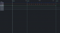
Also here are some low resolution scope images of this communication details are not very visible but it captures the whole frame:
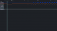
It is also obvious on the image below that the slave in master mode clocks out data significantly slower than HU.
Appendix
Known IDs
| Unit | ID Main Init | ID Response | ID Master Mode | ID When addressed by HU |
|---|---|---|---|---|
| MD (Internal) | 70 | 76 | 77 | 70 or 71 |
| CD (Internal) | 80 | 86 | 87 | 80 or 71 |
| TV (External) | A9 | AE | AF | A8 or A9 |
| DAB (External) | B8 | BE | BF | B8 or B9 |
| SAT (External) | C0 | C6 | C7 | C0 or C1 |
| MD-C (External) | D8 | DE | DF | D8 or D9 |
| CD-C (External) | E8 | EE | EF | E8 or E9 |
Known Commands
| Origin | Destination | Command | Meaning | Response expected |
|---|---|---|---|---|
| HU | CD-C or MD-C | 1E EF | Cartridge Information | Yes - 6 Bytes |
| HU | CD-C or MD-C | 1B E0 01 08 | Track Information | Yes - 9 Bytes |
| HU | CD-C or MD-C | 1B 2D 40 01 | Next Track | No |
| HU | CD-C or MD-C | 1B 2D 00 01 | Previous Track | No |
| HU | CD-C or MD-C | 1A 50 41 | Next CD | No |
| HU | CD-C or MD-C | 1A 50 01 | Previous CD | No |
| HU | CD-C or MD-C | 19 2F | Power Up | Yes - 1 Byte (ack) |
| HU | CD-C or MD-C | 19 22 | Power Down | Yes - 1 Byte (ack) |
| HU | CD-C or MD-C | 19 29 | Fast Forward | Yes - 1 Byte (ack) |
| HU | CD-C or MD-C | 19 26 | Fast Rewind | Yes - 1 Byte (ack) |
| HU | CD-C or MD-C | 19 2E | Scan Mode | Yes - 1 Byte (ack) |
| HU | CD-C or MD-C | 19 52 | Random Mode | Yes - 1 Byte (ack) |


